
10HP 40CFM
Ultra-Dry, Instrument-Grade Compressed Air
Built tough for demanding environments like concrete batch plants, plasma cutting, and precision pneumatic controls.
Built tough for demanding environments like concrete batch plants, plasma cutting, and precision pneumatic controls.
![JP2-H[1]](https://dry-air-systems.com/wp-content/uploads/2026/09/JP2-H1-1.jpg)


| Features | Benefits |
|---|---|
| PDP in excess of −40 °FPressure and flow affect performance | Less than 5% RH for waterborne auto refinishing |
| Designed regeneration | 0.3 micron filtration |
| 110 / 220 volt AC 12 / 24 volt DC |
Custom voltages available |
| Pneumatically controlled option (PDF) | Classified / explosion proof |
| Cartridge-style replacement valves | Modular, expandable design |
| Select purge option (PDF)Reduces regeneration air usage | Spin on / off desiccant cartridges |
| Optional zero-loss condensate auto drain (PDF) | |
The descriptions detailed in this twin tower schematic represent the sequencing of airflow as it relates to the actual drying process and transition – wet to dry – within all dryer systems including both Programmable Logic (PLC) and Pneumatically Controlled (PC) systems

MLT Total Cycle Sequence 240 sec.Cartridge 1 regenerates for 120 sec. |
PLC Total Cycle Sequence 180 sec.Cartridge 1 regenerates for 45 sec. |
PC Total Cycle Sequence 240 sec.Cartridge 1 regenerates for 60 sec. |
Service Schematic AIR-PAK Dryer w/ MLT
(Represents one dryer within MLT dryer system)
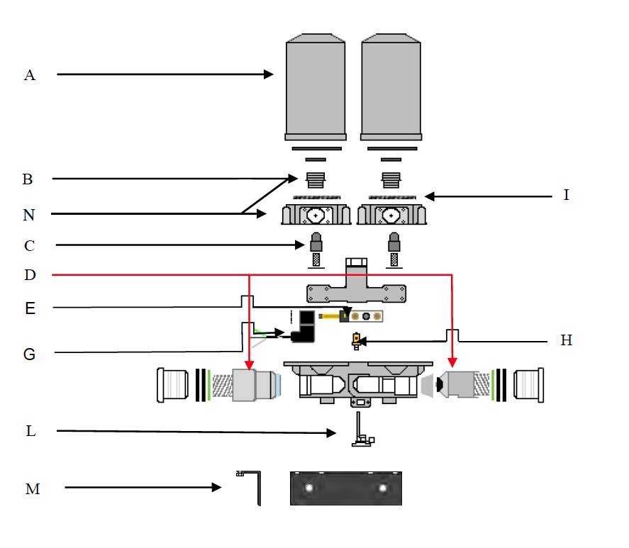
5 – 200 CFM dryer systems
Scroll sideways to see all dryer sizes & kit contents
| Illustration | Part Number | Ref | Air-Pak w/ 4 lb. Desiccant Cartridges | Contents of Service Kit | ||
|---|---|---|---|---|---|---|
| 2 | 4 | 6 | ||||
 |
619832 | A | 1 | 2 | 3 | Grey Cartridges – Full Service KitIncludes 2 each desiccant cartridges, inlet & purge valves |
| 619700 | A | 1 | 2 | 3 | Blue Cartridges – Full Service KitIncludes 2 each desiccant cartridges, inlet & purge valves | |
| 619950 | A | 1 | 2 | 3 | White Cartridges – Full Service KitIncludes 2 each desiccant cartridges, inlet & purge valves | |
| 619830 | A | 1 | 2 | 3 | Grey Desiccant Cartridge KitIncludes 2 desiccant cartridges | |
| 619704 | A | 1 | 2 | 3 | Blue Desiccant Cartridge KitIncludes 2 desiccant cartridges | |
| 619951 | A | 1 | 2 | 3 | White Desiccant Cartridge KitIncludes 2 desiccant cartridges | |
 |
619702 | D | 1 | 2 | 3 | Valve Service KitIncludes 2 inlet check valves, 2 purge valves |
 |
619708 | C | 1 | ~ | ~ | .014 Regeneration Valve Kit |
| 619715 | C | ~ | 2 | ~ | .030 Regeneration Valve Kit | |
| 619730 | C | ~ | ~ | 3 | .060 Regeneration Valve Kit | |
 |
619755 | E | 1 | 1 | 1 | Air Control Valve – Two air lines |
 |
619790 | G | 1 | 2 | 3 | 110 Volt Micro Logic Timer (MLT) |
| 619912 | G | 1 | 2 | 3 | 12 VDC Micro Logic Timer (MLT) | |
| 619924 | G | 1 | 2 | 3 | 24 VDC Micro Logic Timer (MLT) | |
 |
619740 | H | 1 | 2 | 3 | Pressure Relief Valve |
 |
619750 | L | 1 | 2 | 3 | 110 VAC Heater Kit (optional) |
| 619782 | L | 1 | 2 | 3 | 12 VDC Heater Kit (optional) | |
| 619784 | L | 1 | 2 | 3 | 24 VDC Heater Kit (optional) | |
 |
619860 | I | 1 | 2 | 3 | .3 Micron Disc Filter |
 |
619760 | B | 2 | 4 | 6 | Cartridge Stud for Grey Canisters |
| 619765 | B | 2 | 4 | 6 | Cartridge Studs for Blue, White, Canisters | |
 |
619734 619735 619736 619737 |
N N N N |
1 1 1 |
2 2 2 2 |
3 3 3 3 |
Right Side Blue + White Canister Left Side Blue + White Canister Left Side Grey Canister Right Side Gray Canister Adapter Plate + Stud Together |
 |
619770 | — | 1 | 2 | 3 | Small Mufflers (optional) |
| 619915 | — | 1 | 2 | 3 | Large Mufflers (optional) | |
| Not shown | 619942 | — | 1 | ~ | ~ | Wall Strut w/ slot for two cartridge dryer system |
 |
619990 | M | 1 | 2 | 3 | Wall Mount Bracket |
Many other sizes available upon request