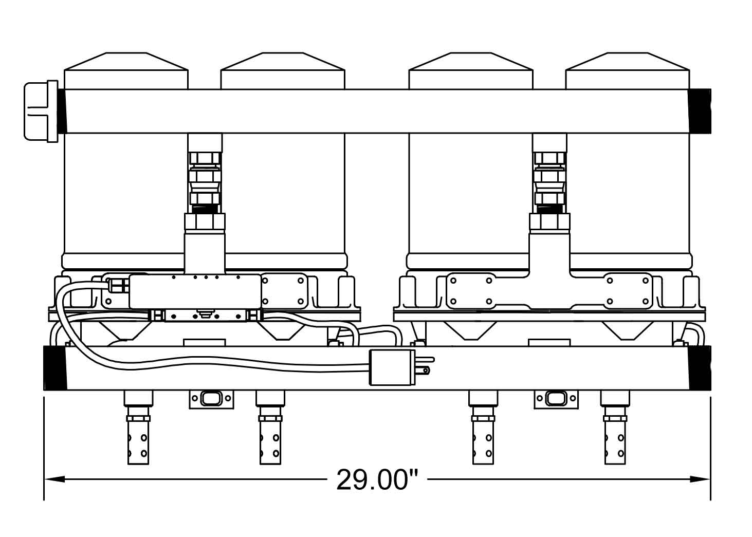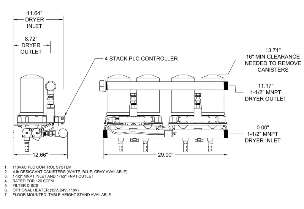
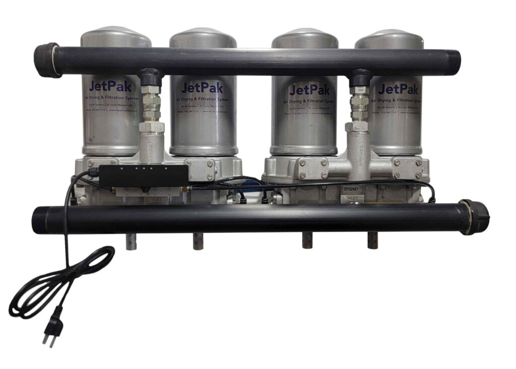
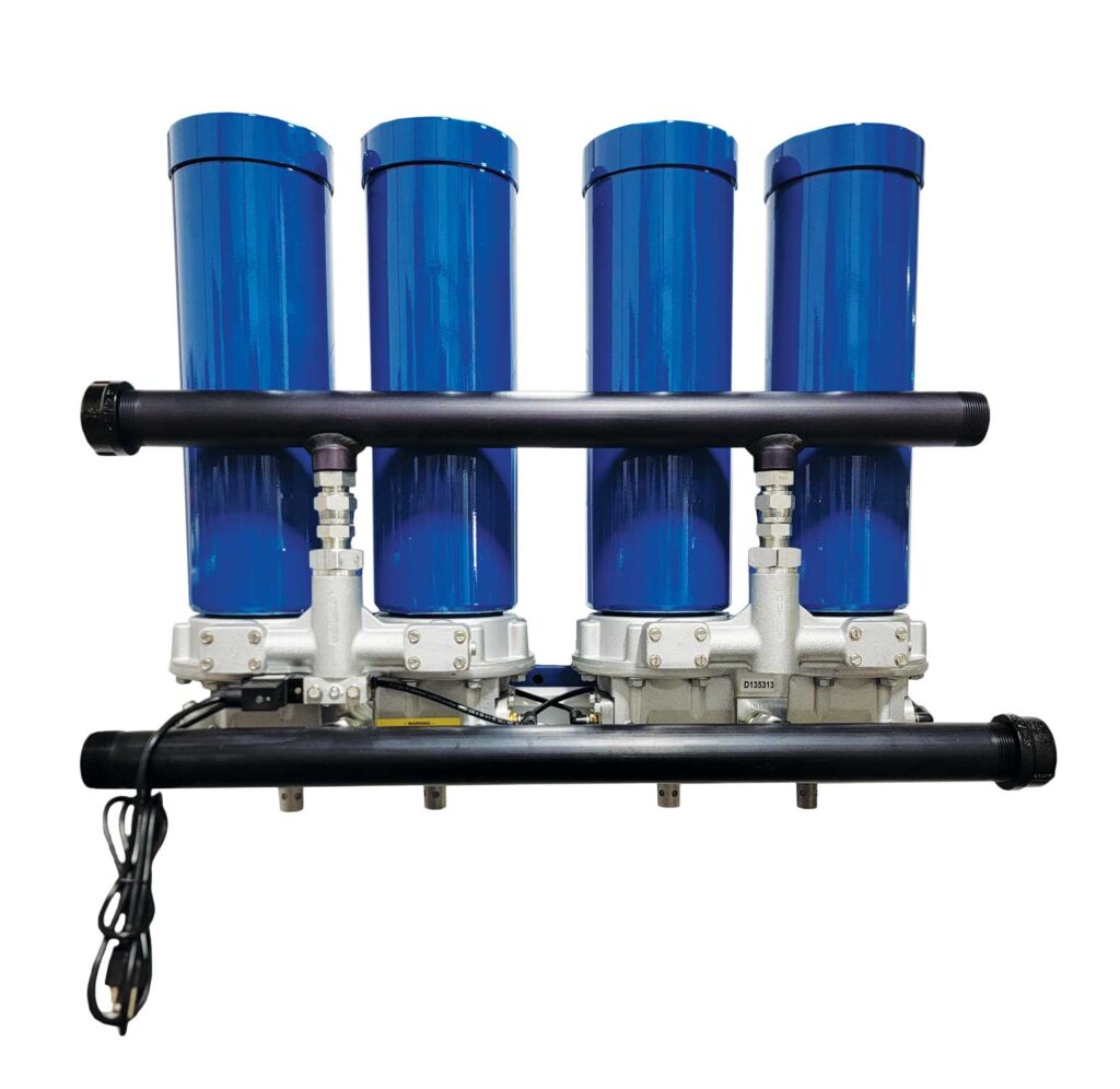
30HP 120CFM
Precision Dried Instrument Quality Air
Engineered for the punishing demands of ready-mix concrete, cement batching, plasma cutting, and critical instrument air applications.
![]() |
Features | Benefits |
|---|---|---|
| PDP In Excess Of -40°F* *pressure and flow affect performance |
1.5″ Inlet/Outlet Ports | |
| Designed Regeneration | .3 Micron Filtration | |
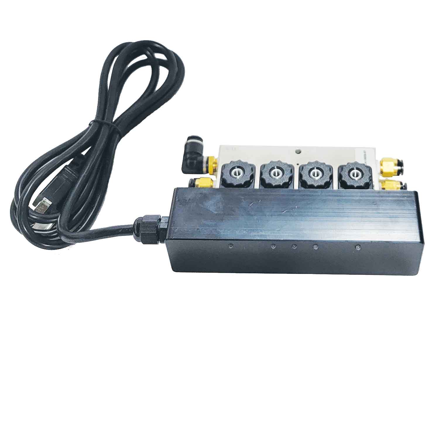
| 110, 220 Volt AC 12, 24, Volt DC |
Custom Voltages Available | |
| Pneumatically Controlled Option | Classified / Explosion Proof | |
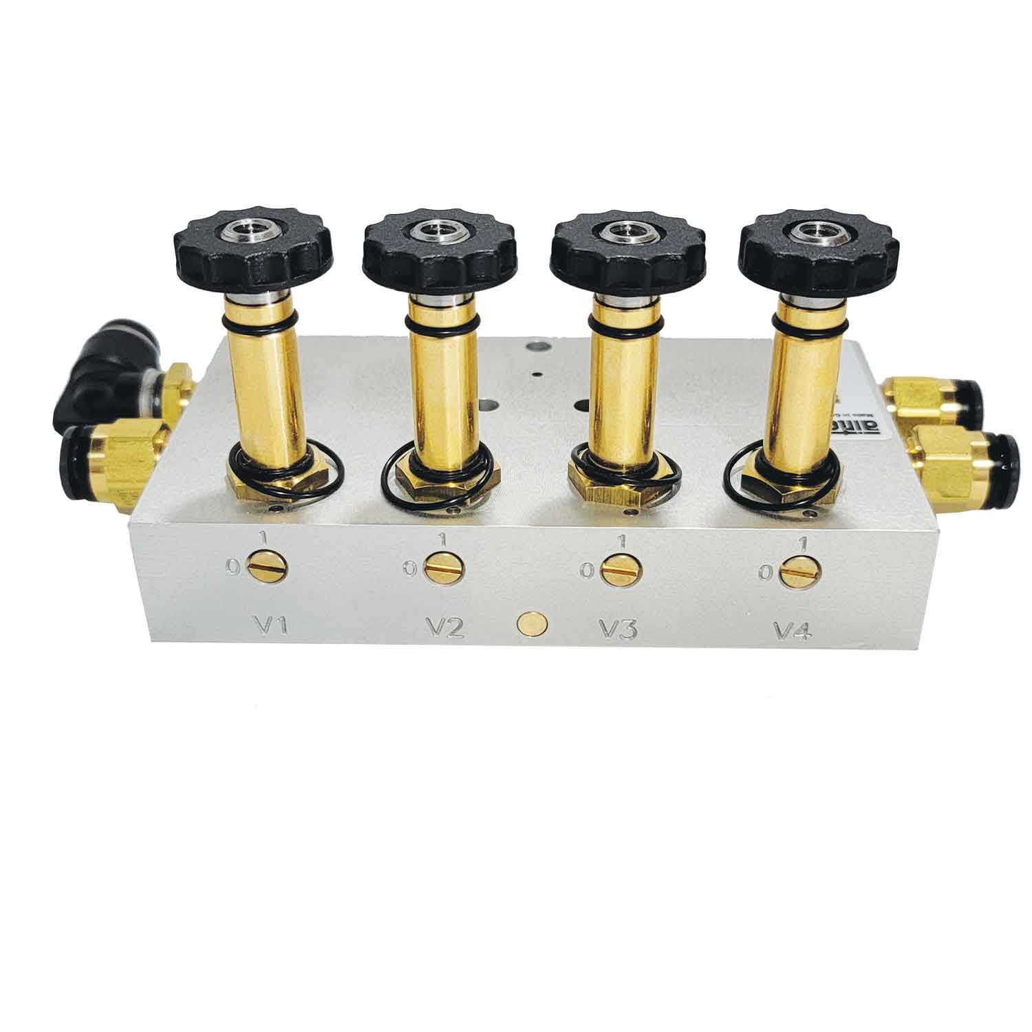
| Cartridge Style Replacement Valves |
Modular Design Expandable |
|
| Select Purge Option* Saves Regeneration Air Usage |
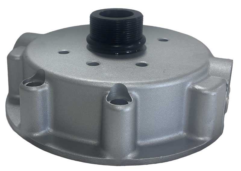
Spin On/Off Desiccant Cartridges |
|
| Optional Zero Loss Condensate Auto Drain | ||
|
Regeneration Orifice .060 -P4C = .060 orifice |
Max Flow@ 100% Duty Cycle 120 CFM |
Max Flow@ 70% Duty Cycle 84 CFM |
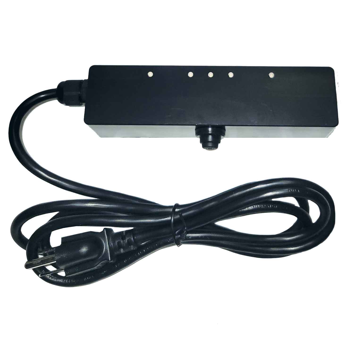
REMINDER: PC controller not illustrated however, distributes pilot signals in same sequence as a PLC controller.
The descriptions detailed on page “Twin Tower w/MLT” schematic represents the sequencing of air flow as it relates to the actual drying process and transition – wet to dry – within all dryer systems including Programmable Logic (PLC) and Pneumatically Controlled (PC) systems.
PLC Total Cycle Sequence 180 sec.Cartridge 1 regenerates for 45 sec. Cartridge 2, 3, 4 receives wet air. PLC switches Cartridge 2 regenerates for 45 sec. Cartridge 1, 3, 4 receives wet air. PLC switches |
PC Total Cycle Sequence 240 sec.Cartridge 1 regenerates for 60 sec. Cartridge 2, 3, 4 receives wet air. PC switches Cartridge 2 regenerates for 60 sec. Cartridge 1, 3, 4 receives wet air. PC switches |
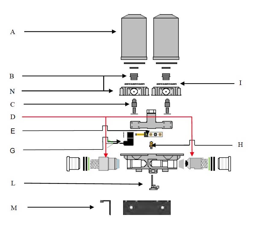
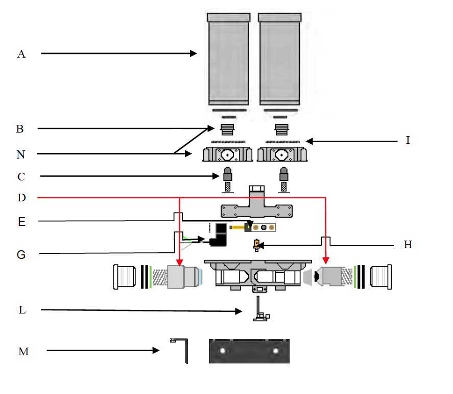
(Represents one dryer with PLC dryer system)
1. Identify dryer system by counting numbers of desiccant cartridges, e.g., 2, 4, 6
2. Locate service component identity, e.g., A, B, C, etc.
3. Under “Qty”, order appropriate number of kits specific to cartridge total
download Service Schematic(Represents one dryer with MLT dryer system)
1.Identify dryer system by counting numbers of desiccant cartridges, e.g., 2, 4, 6
2.Locate service component identity, e.g., A, B, C, etc.
3.Under “QTY”, order appropriate number of kits specific to cartridge totals
Download Service Schematic