Lorem ipsum dolor sit amet, consectetuer adipiscing elit, sed diam nonummy nibh euismod tincidunt ut laoreet dolore magna aliquam erat volutpat.
Lorem ipsum dolor sit amet, consectetuer adipiscing elit, sed diam nonummy nibh euismod tincidunt ut laoreet dolore magna aliquam erat volutpat.

| Bluetooth technology | |
|---|---|
| Records number of dryer cycles | Will not drain air from system overnight |
| Tracks service history | Service updates sent by text message |
| Selectable timed regeneration cycles | 90-second cycle for high flow120-second cycle for moderate flow |
| Regenerates only when compressor is pumping | Test cycles for service analysis |
| Installs on Air Pak dryers currently in service | Cartridge-style replacement valves |
| 0.3 micron filtration | Spin on / off desiccant cartridges |
| Optional zero-loss condensate auto drain (PDF) | |
The descriptions detailed in this twin tower schematic represent the sequencing of airflow as it relates to the actual drying process and transition – wet to dry – within all dryer systems including both Programmable Logic (PLC) and Pneumatically Controlled (PC) systems

Service Schematic AIR-PAK Dryer w/ PLC
(Represents one dryer within PLC dryer system)
|
<...e Sequence 180 sec.
Cartridge 1 regenerates for 45 sec. Cartridge 2, 3, 4 receives wet air. PLC switches Cartridge 2 regenerates for 45 sec. Cartridge 1, 3, 4 receives wet air. PLC switches |
PC Total Cycle Sequence 240 sec.Cartridge 1 regenerates for 60 sec. Cartridge 2, 3, 4 receives wet air. PC switches Cartridge 2 regenerates for 60 sec. Cartridge 1, 3, 4 receives wet air. PC switches |
Drag or scroll horizontally to see full table
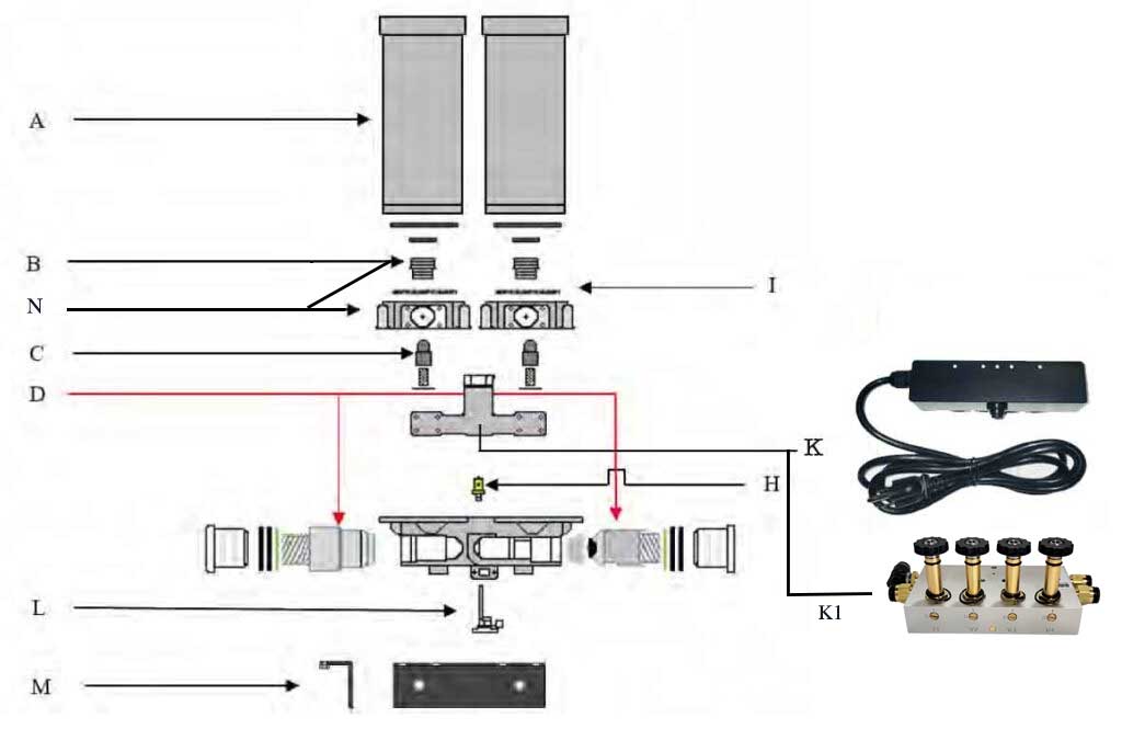
| Illustration | Part Number | Ref | Air-Pak HC w/ 8lb. Desiccant Cartridges | Contents of Service Kit | |||||
|---|---|---|---|---|---|---|---|---|---|
| 2 or 4 | 6 | 10 | 12 | 18 | 24 | ||||
 |
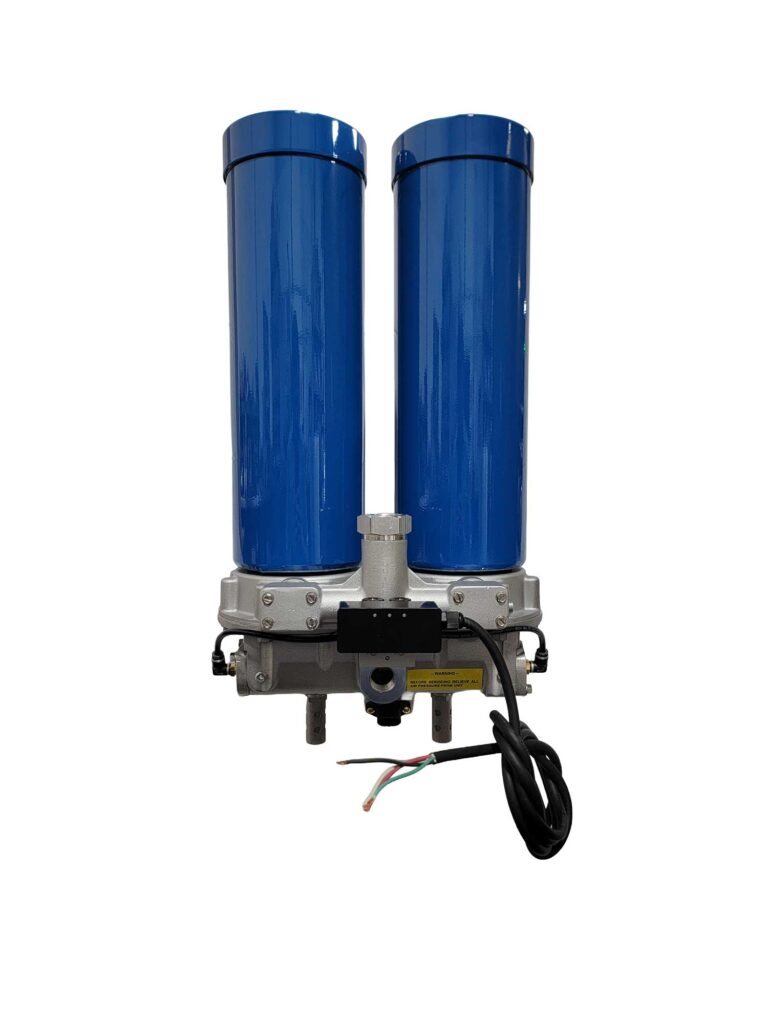
650830 | A | 2 | 3 | 5 | 6 | 9 | 12 | Grey Cartridges – Full Service Kit Includes 2 each desiccant cartridges, inlet & purge valves |
| 650700 | A | 2 | 3 | 5 | 6 | 9 | 12 | Blue Cartridges – Full Service Kit Includes 2 each desiccant cartridges, inlet & purge valves |
|
| 650951 | A | 2 | 3 | 5 | 6 | 9 | 12 | White Cartridges – Full Service Kit Includes 2 each desiccant cartridges, inlet & purge valves |
|
| 4055A002 | A | 2 | 3 | 5 | 6 | 9 | 12 | Grey Desiccant Cartridge Kit Includes 2 desiccant cartridges |
|
| 4055A020 | A | 2 | 3 | 5 | 6 | 9 | 12 | Blue Desiccant Cartridge Kit Includes 2 desiccant cartridges |
|
| 4055A012 | A | 2 | 3 | 5 | 6 | 9 | 12 | White Desiccant Cartridge Kit Includes 2 desiccant cartridges |
|
 |
619702 | D | 2 | 3 | 5 | 6 | 9 | 12 | Valve Service Kit Kits includes 2 inlet check valves, 2 purge valves |
 |
619730 | C | 1 | 3 | 5 | 6 | 9 | 12 | .060 Regeneration valve kit |
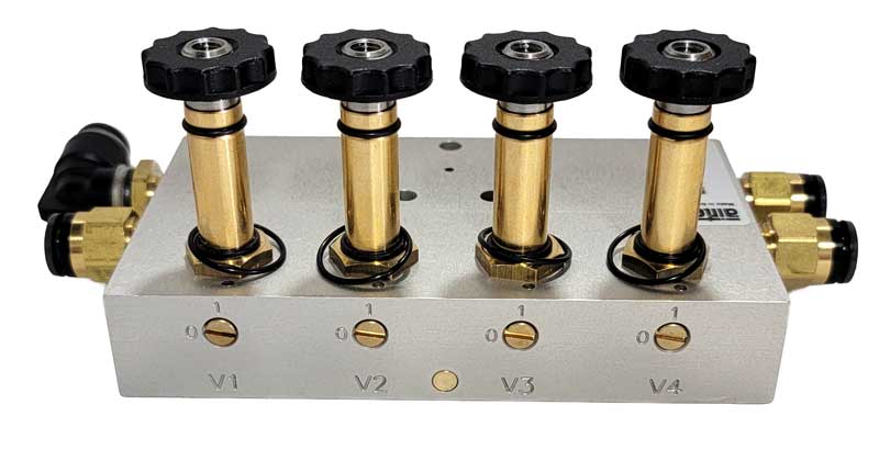 |
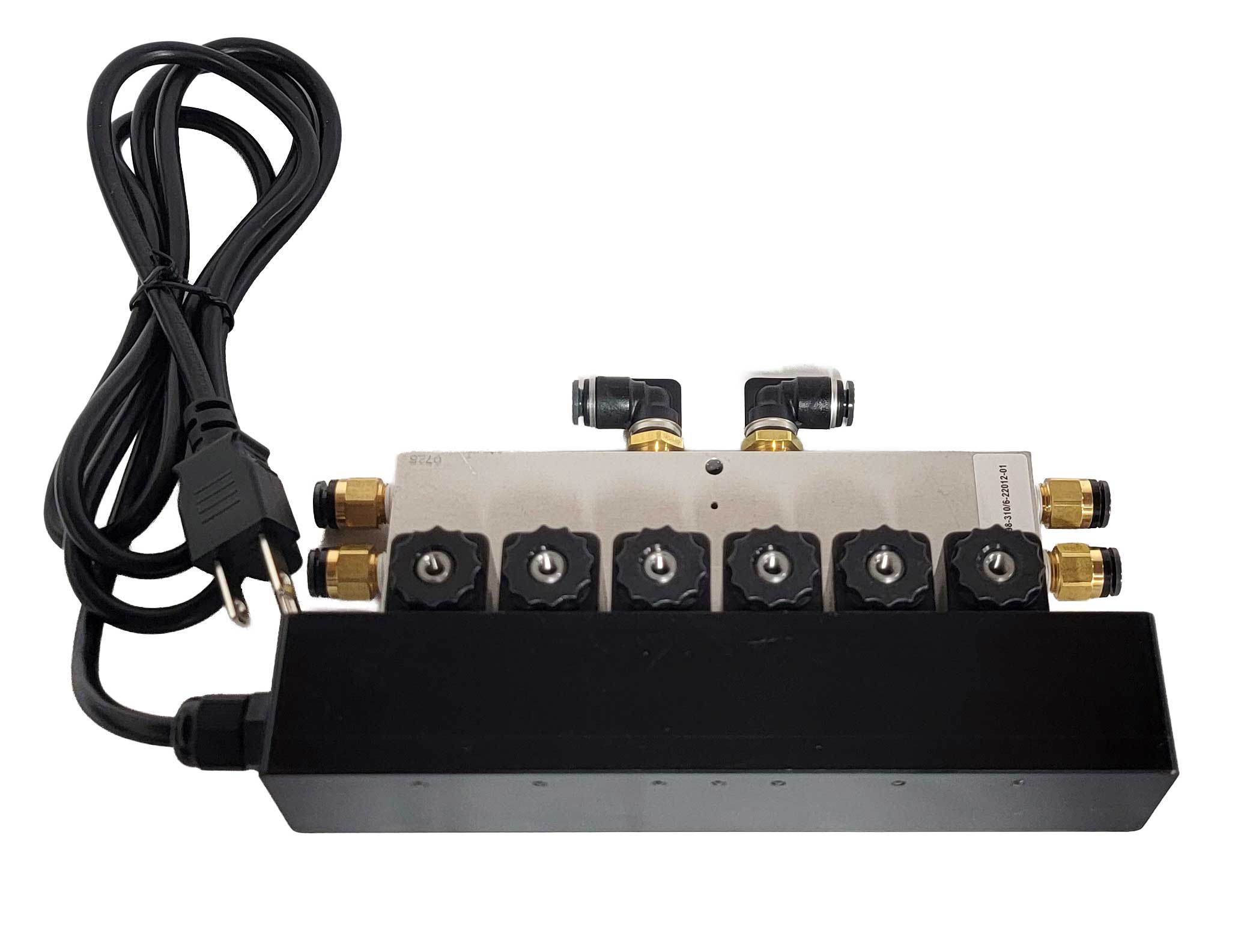
619717 | K1 | 1 | 1 | 1 | 1 | 1 | 1 | Air Control Valve For 2 Solenoid PLC |
| 619812 | K1 | 1 | 1 | Air Control Valve For 4 Solenoid PLC | |||||
| 619820 | K1 | 1 | 1 | 1 | 1 | Air Control Valve For 6 Solenoid PLC | |||
|
|
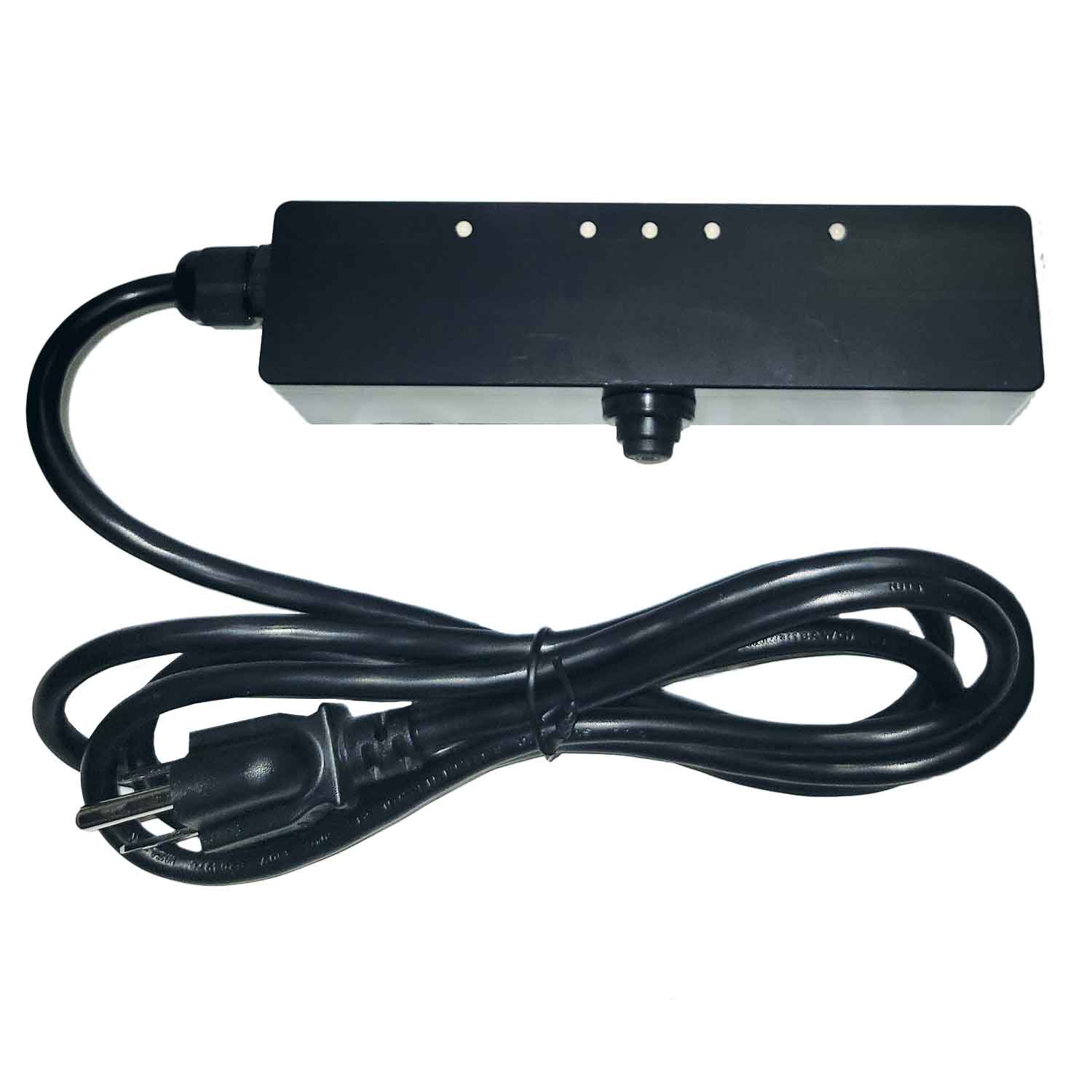
619714 | K | 1 | 1 | 1 | 1 | 1 | 2 Solenoid – 110 Volt Programmed Logic Controller – Electronics Only | |
| 619824 | K | 1 | ~ | 1 | ~ | 1 | 4 Solenoid – 110 Volt Programmed Logic Control – Electronics Only | ||
| 619937 | K | 1 | ~ | ~ | ~ | ~ | ~ | 6 Solenoid – 110 Volt Programmed Logic Control – Electronics Only | |
|
|
619814 | K&K1 | 1 | 1 | 1 | 1 | 1 | 1 | 2 Solenoid Select Purge PLC |
| 619815 | K&K1 | 1 | ~ | 1 | ~ | 1 | 1 | 4 Solenoid Programmable Logic Controller | |
| 619816 | K&K1 | ~ | 1 | ~ | 1 | 1 | 1 | 6 Solenoid Programmable Logic Controller | |
 |
619740 | H | 2 | 3 | 5 | 6 | 9 | 12 | Pressure Relief Valve |
 |
619750 | L | 2 | 3 | 5 | 6 | 9 | 12 | 110 VAC Heater Kit (optional) |
| 619782 | L | 2 | 3 | 5 | 6 | 9 | 12 | 12 VDC Volt Heater Kit (optional) | |
| 619784 | L | 2 | 3 | 5 | 6 | 9 | 12 | 24 VDC Volt Heater Kit (optional) | |
 |
619760 | I | 1 | 3 | 5 | 6 | 9 | 12 | Disc Filter |
 |
619760 | B | 4 | 6 | 10 | 12 | 18 | 24 | Cartridge Stud for Grey Cartridges |
| 619765 | B | 4 | 6 | 10 | 12 | 18 | 24 | Cartridge Studs for Blue, White, Purple Cartridges | |
 |
619734 | N | 1 | 2 | 3 | ~ | ~ | ~ | Right Side Blue + White Canister Adapter Plate + Stud Together |
| 619735 | N | 1 | 2 | 3 | ~ | ~ | ~ | Left Side Blue + White Canister Adapter Plate + Stud Together |
|
| 619736 | N | 1 | 2 | 3 | ~ | ~ | ~ | Left Side Grey Canister Adapter Plate + Stud Together |
|
| 619737 | N | ~ | 2 | 3 | ~ | ~ | ~ | Right Side Grey Canister Adapter Plate + Stud Together |
|
 |
619770 | ~ | 4 | 6 | 10 | 12 | 18 | 24 | Small Mufflers (optional) |
| 619915 | ~ | 4 | 6 | 10 | 12 | 18 | 24 | Large Mufflers (optional) | |
 |
619942 | ~ | 1 | ~ | ~ | ~ | ~ | ~ | Wall Strut w/slot for two cartridge dryer system |
 |
619990 | M | 2 | 3 | 5 | 6 | 9 | 12 | Wall Mount Bracket |
Wiring guides
Three ways to connect your dryer. Tap any diagram to enlarge it, or download the PDF for each option.
OPTION 01
Connecting the 4-wire system to the air compressor’s pressure control.

Operation check
OPTION 02
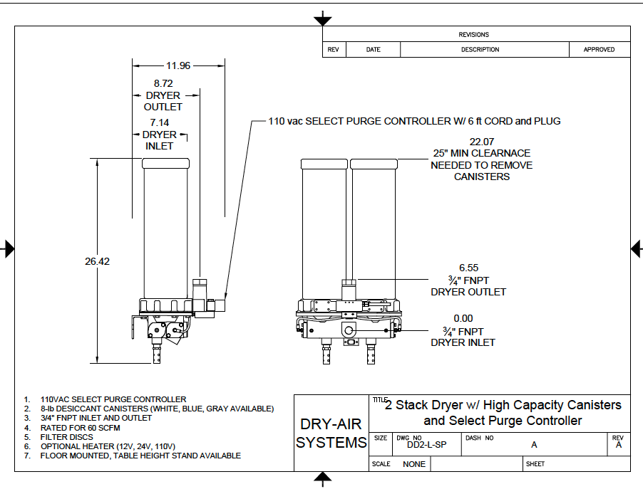
For a dryer installed at point of use, e.g., a paint booth. Air-Pak Select Purge can connect directly to a 110 V dedicated switch.

OPTION 03
For a dryer installed at point of use, e.g., a paint booth. Air-Pak Select Purge can connect directly to a 110 V dedicated switch.

Custom sizing
Many other sizes available upon request.

Redi-Mix Plants
Cement Batch Plants
Plasma Cutting
Instrument Air
Point Of Use Manufacturing
Packaging Equipment
Paint Booths
Maintenance Equipment
Repair Shops
Spray Foam Insulation